Handibot Rotary Indexer
by David Bryan • August 4, 2014 • Handibot Labs • 5 Comments
![]()

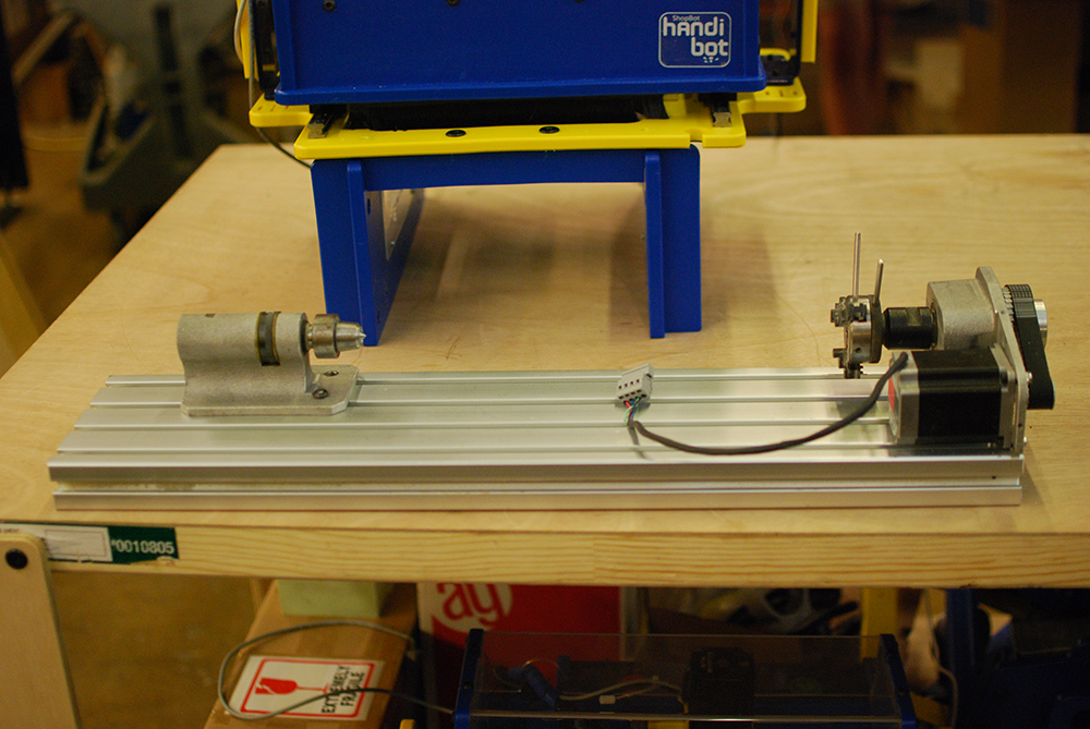
To kick off Handibot Labs, let’s take a look at the Handibot 4-axis accessory. We launched the concept at this year’s MakerCon and Maker Faire, San Mateo alongside the 5-axis accessory (expect a future Labs blog post on 5-axis). This Make: magazine interview with Ted Hall offers a quick look at our MakerCon first showing of the 4-axis and 5-axis. I’ll use this post to give a more detailed view of the 4-axis and how to setup for rotary machining with Handibot by working through a sample project. In the process, you will see what Handibot is capable of in terms of machining in the round. And, perhaps you will learn whether rotary machining would be a good addition to your toolkit for making. So, let’s take a look at the hardware.
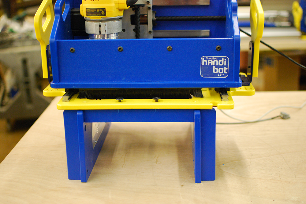
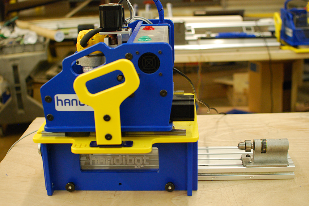
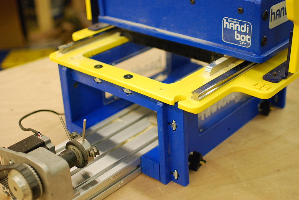
The first task is to block up the Handibot to allow an indexer to be slid beneath. Below is our first prototype made from HDPE with a variant of Handibot joinery; that means these parts can be easily cut with a ShopBot.
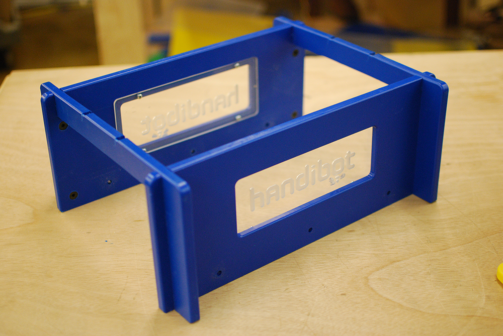
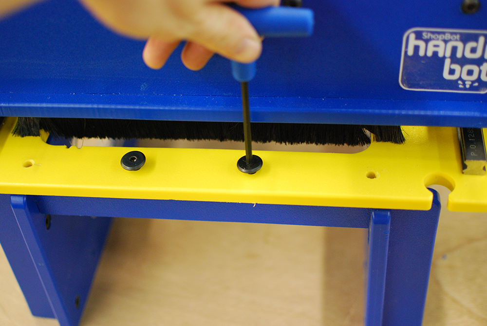
The Handibot is attached using 2 holes at the front and 2 holes at the rear of the baseplate. This provides a secure attachment and eliminates the possibility of the tool lifting while machining.
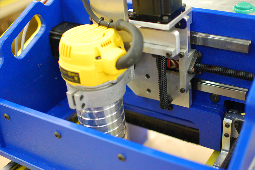
To reach the center line of the part with a reasonable length cutter, the router is slid down in its bracket. The dust collection tray is removed to allow the router body sufficient space to plunge.
Our 3″ indexer is mounted to an extrusion using t-nuts in slots. The extrusion can be any length, in theory, for long turnings using tiled toolpaths. We’ll look at tiled rotary toolpaths in a future blog post. The challenge with any toolpath tiling is accurately moving to the next tile to avoid a “bump” at the transition. We’ll need to look closely at the feasibility of being able to do so before being able to make any definitive claims related to tiling rotary toolpaths.
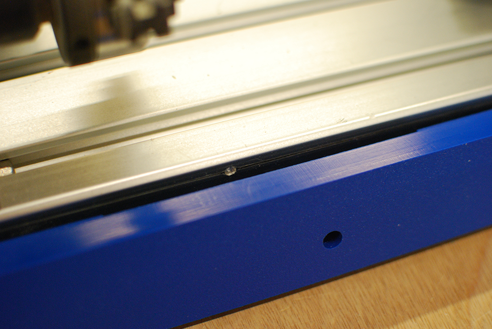
We’ve worked on the assumption that we will be able to accurately tile rotary toolpath, so we’ve included features to help with accurate repositioning. The image below shows a ball detent that is integrated into one of the spacers the extrusion slides between.

The ball detent falls into dimples milled into the extrusion at precise intervals.
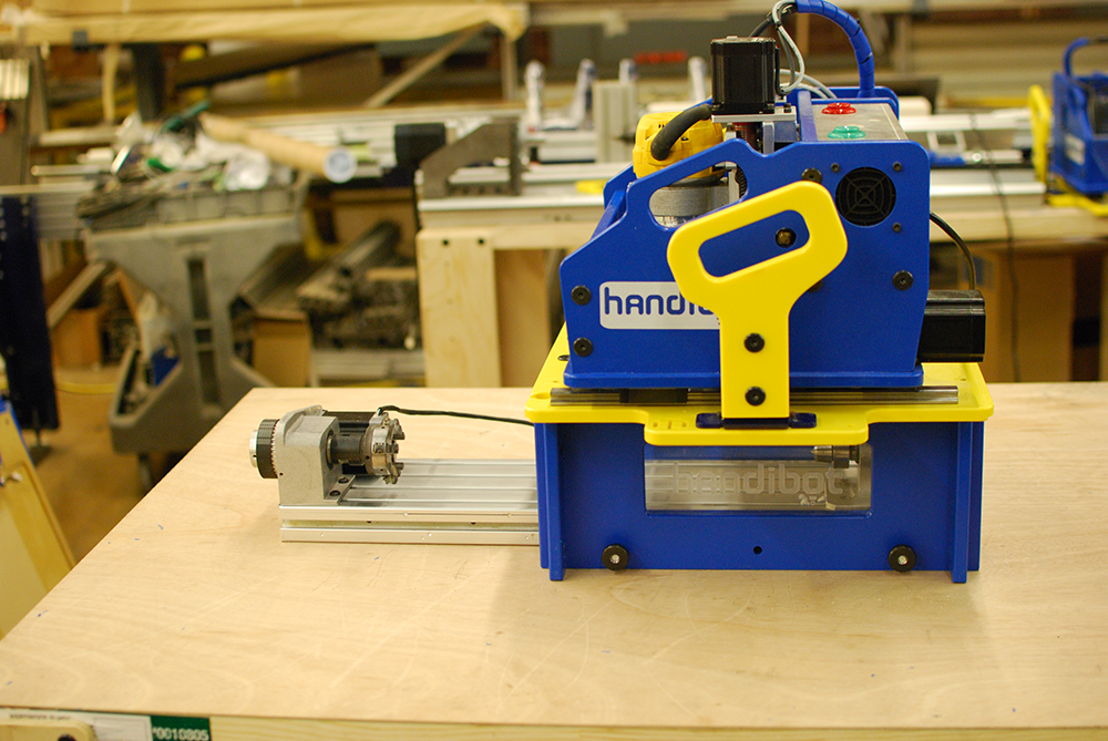
Spacers are stacked with the inner spacer machined to ride in the t-slot. Knobs on the side of the frame close the gaps and secure the extrusion.
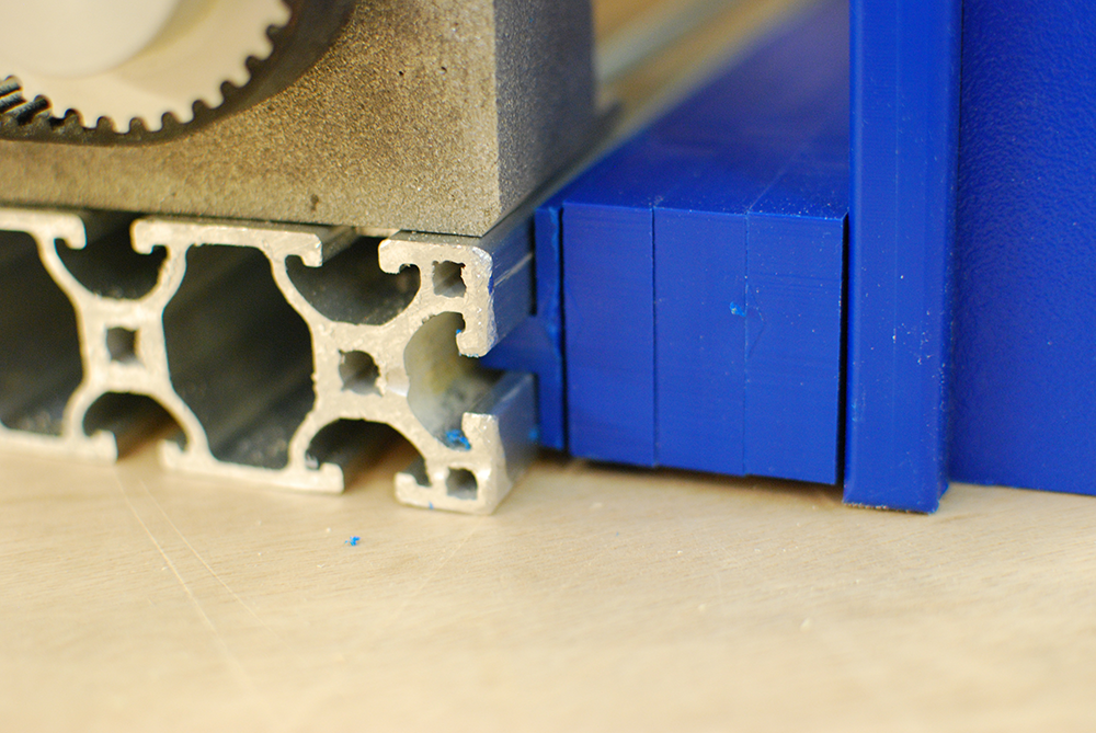
The knobs are threaded onto carriage bolts that also ride in the t-slots.
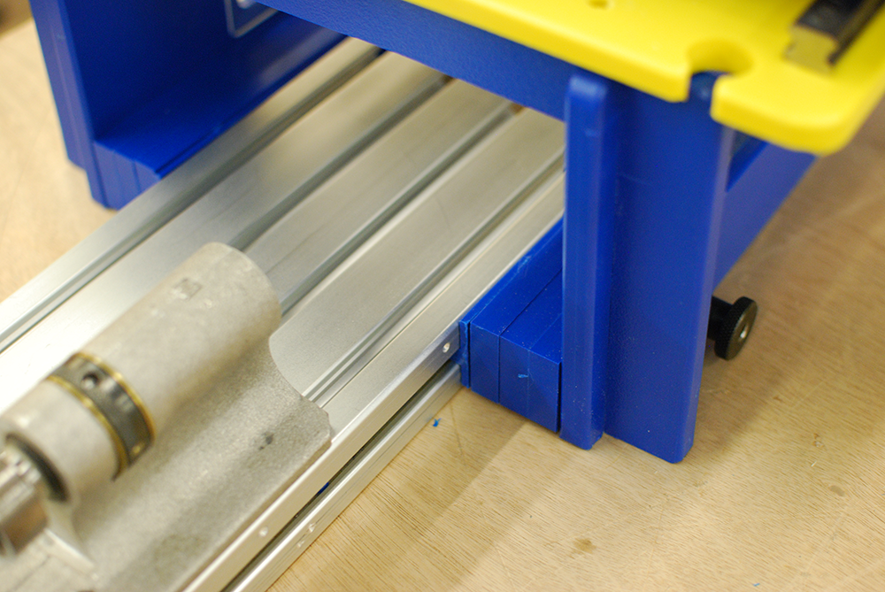
Loosening the side knobs allows the extrusion to be repositioned beneath the tool for part loading and unloading. This feature is also what will allow tiled jobs.

To demonstrate the capabilities of the tool I’ll be making a small bust of the Venus de Milo statue. This project involves milling a form with complex curves and a high level of detail that combine to show off Handibot’s capabilities nicely. Rotary machining begins with a digital, 3D model; most often you’ll create your own 3D model in the CAD software of your choice and export the geometry in .STL or .OBJ format. If you aren’t up for creating your own 3D model, there are many places on the web to download 3D models. The model of Venus de Milo that I use here came from Deskproto [link], but check out Thingiverse, Turbosquid, among others, for 3D models of nearly anything imaginable. You can also check out our 100K Garages site if you’d like to find a designer to create a 3D model of your project for you.
Once you have a 3D model, you are ready to begin generating a toolpath, the set of instructions used to move the tool. There are several ways to generate 4 axis toolpaths; we’ll see the continuous 4-axis method throughout this post. I’ll also mention rotary-indexed machining, another option that we will cover in a future blog post. For continuous 4-axis toolpath generation, I use a piece of software called DeskProto. DeskProto is marketed as “3D machining for non-machinists,” which translates into a fairly easy-to-use piece of software with an attractive price point at around 3 for a hobbyist license. Continuous 4- axis machining is attractive due to the minimal setup requirements; typically there is only a roughing operation and finishing operation performed on all sides of the model in one setup. Indexed machining, on the other hand, requires a roughing and finishing operation to be performed on 2 or 4 sides of the model individually, with manually-programmed part rotations between setups. While the indexed approach takes a little longer to setup, it is not without its benefits, namely cost savings. Handibot owners who purchased their tool after our Kickstarter campaign already have the software needed for indexed machining, Cut3D. Our Kickstarter backers can still get Cut3D, at a discount, by emailing us at store@handibot.com and mentioning this post.
Below, I’ve captured the steps I took to machine the Venus de Milo bust in a block of poplar. For those interested in eventually purchasing or making their own indexer for Handibot, this might serve as a good first project.
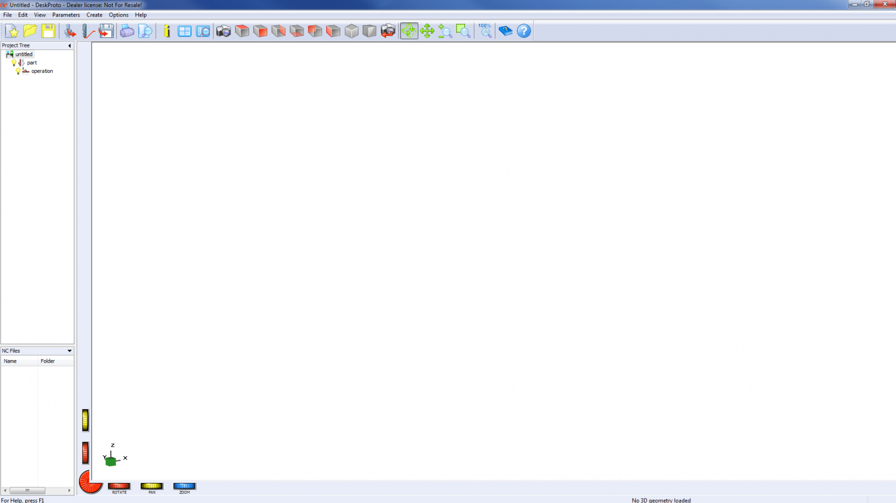
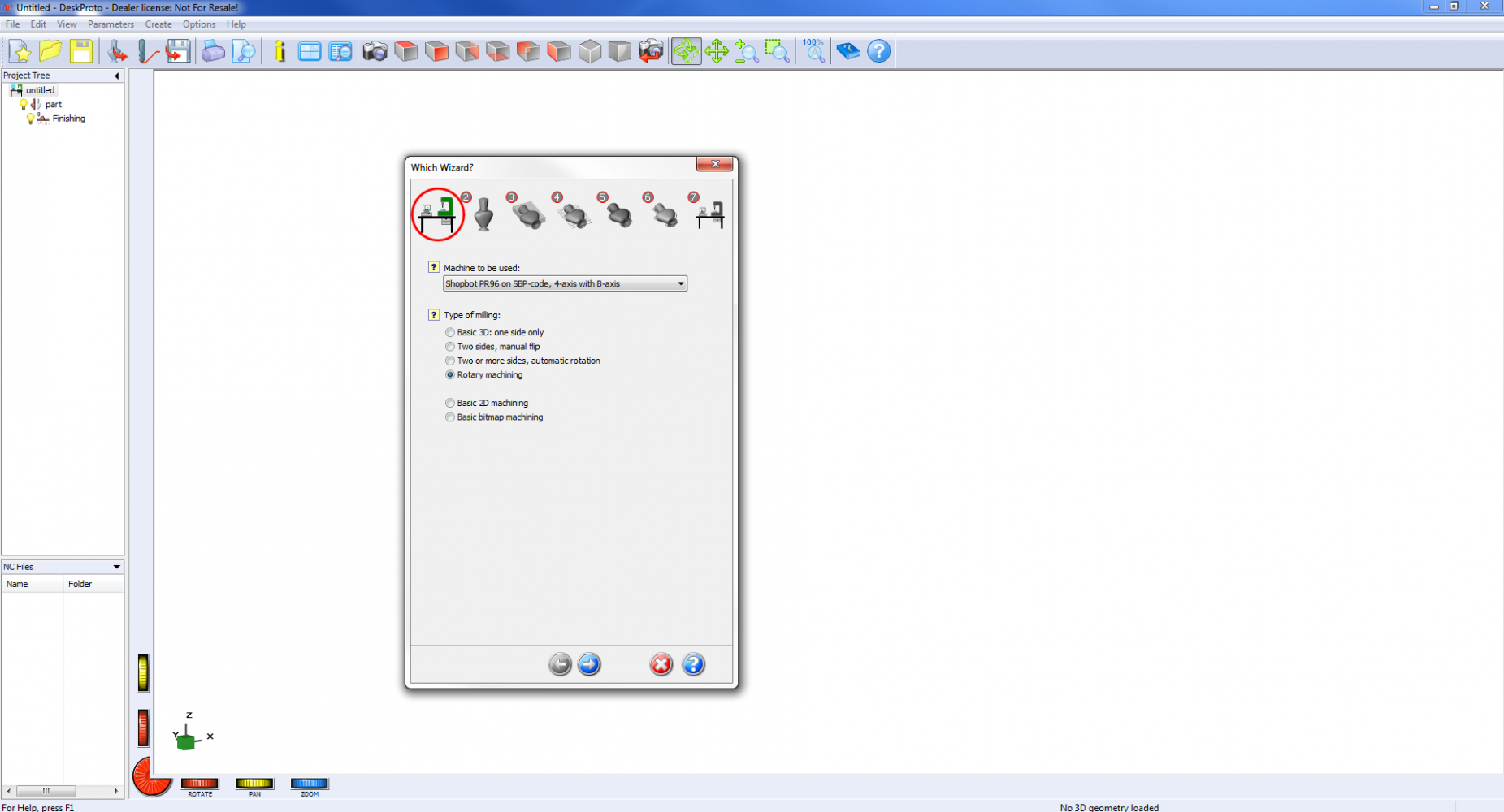
First, launch the software to open a blank canvas.
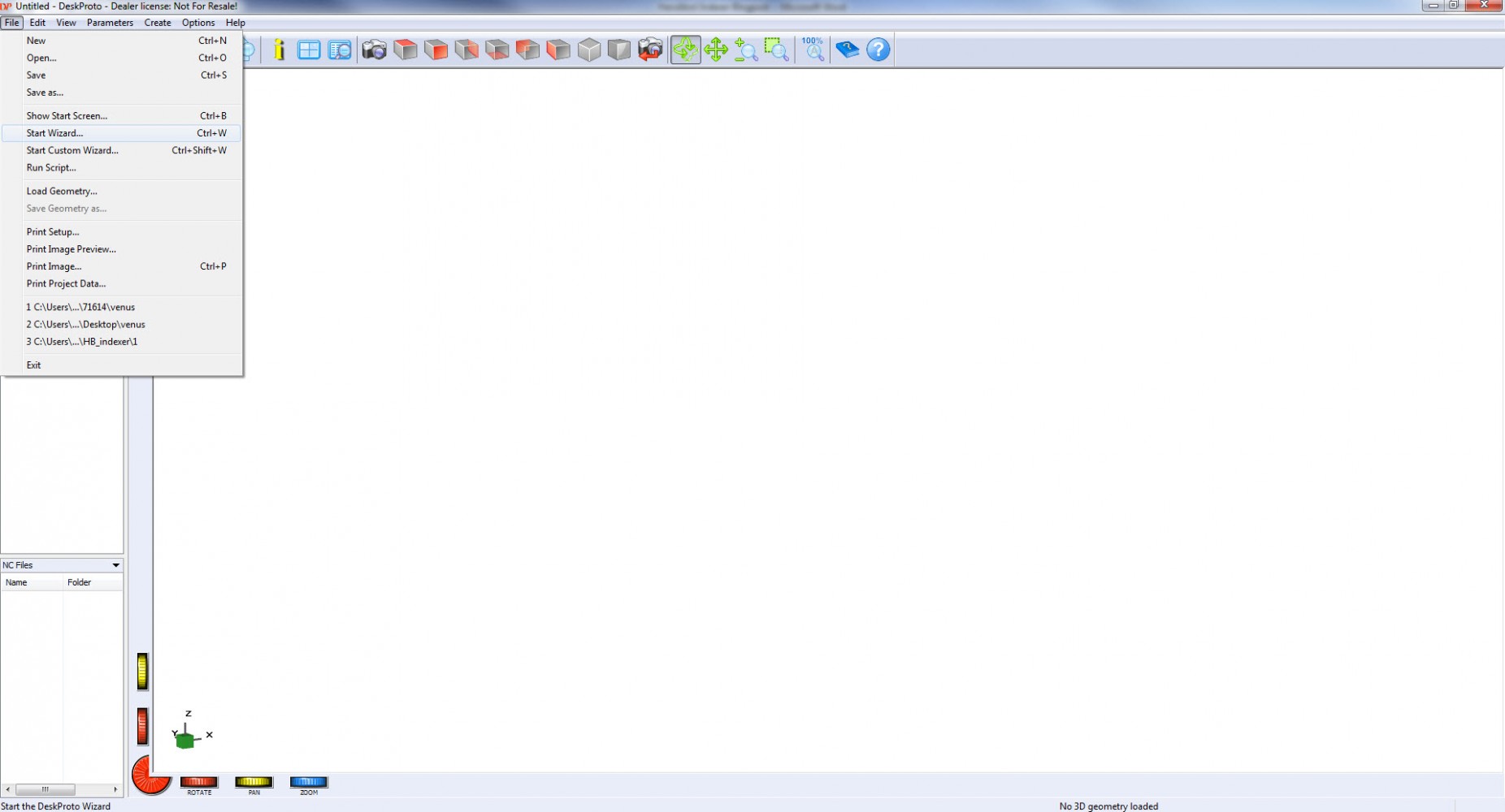
Go to the File dropdown menu and select Start Wizard
Choose the following settings:
Machine to be used:
ShopBot PR96 on SBP-code, 4-axis with B-axis
Type of milling:
Rotary machining
Click Blue Next arrow at bottom
Browse to the location where your 3D model is stored
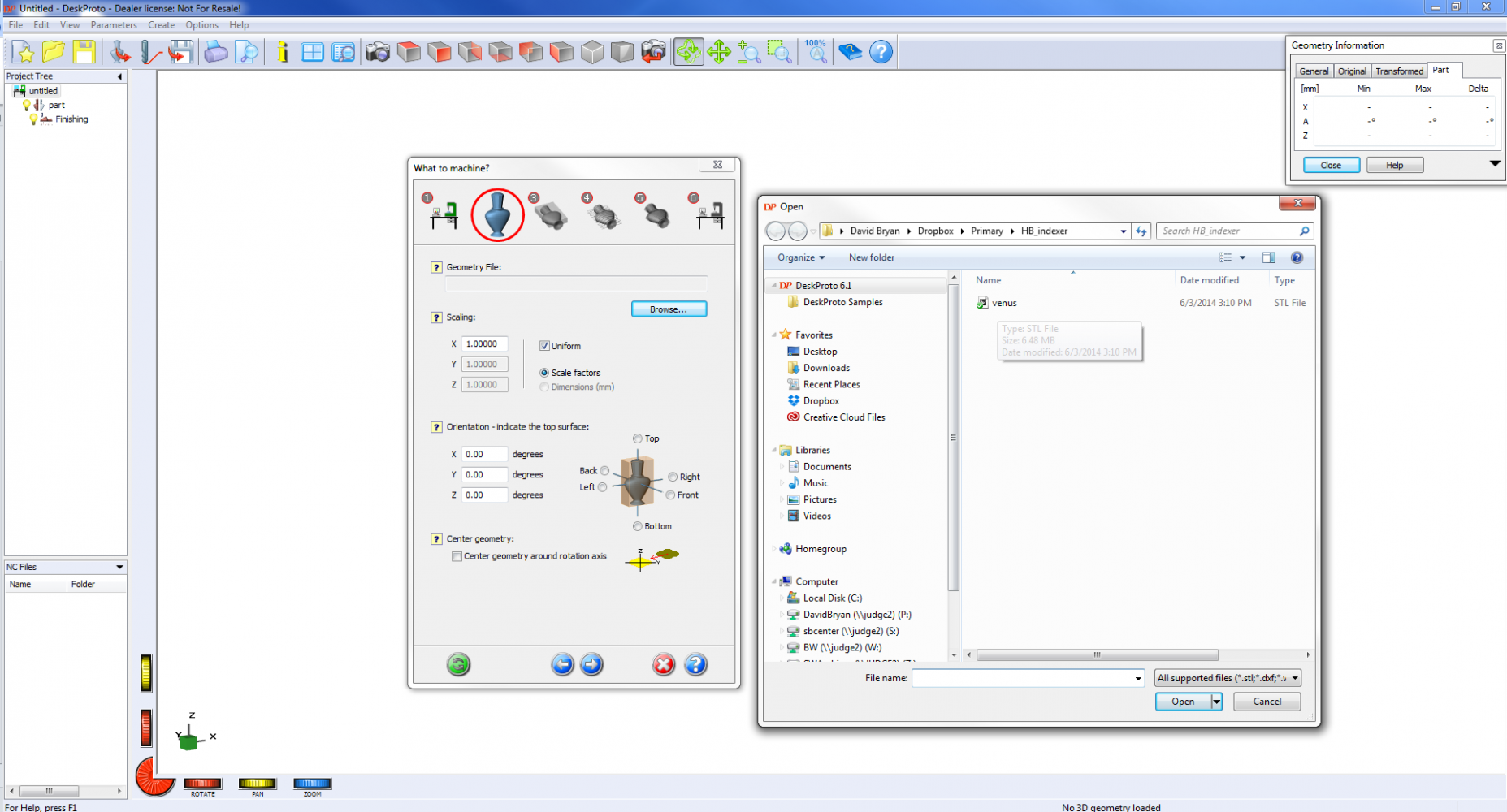
Use Scaling to set the model size to match the material you intend to use for your project
Here, I’m using a poplar glue-up which measures 2.5”x 2.5”x 8”. You want to scale the model such that it fits comfortably inside the material dimensions.
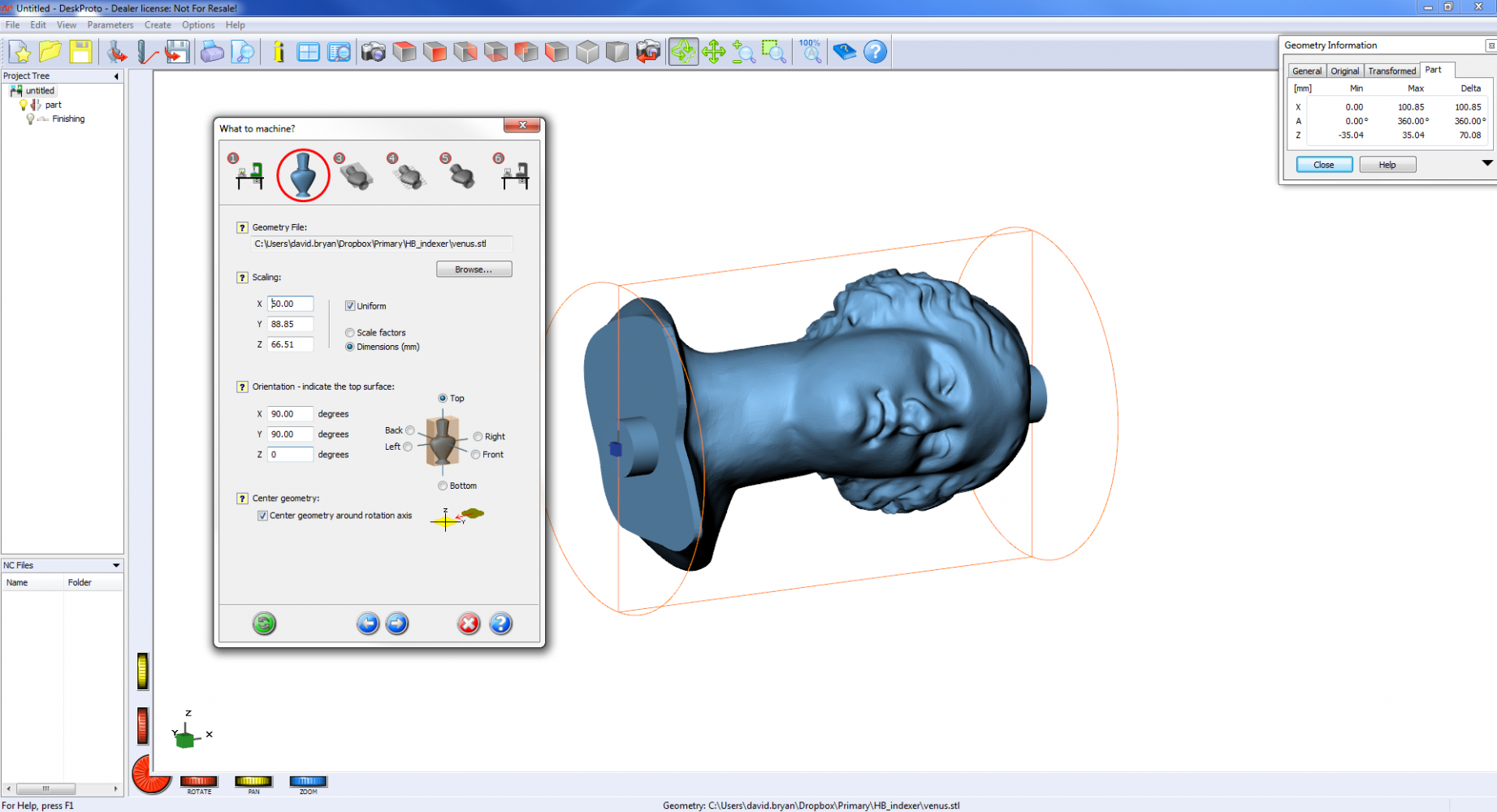
Next, orient geometry so that model will rotate about X axis.
Note: although we are setting the model orientation such that the trident in the lower left corner indicates part rotation about the X axis, the posted code will actually rotate the part about the Y axis, exactly what is needed for Handibot.
Check the box for Center geometry about axis of rotation
Click Next
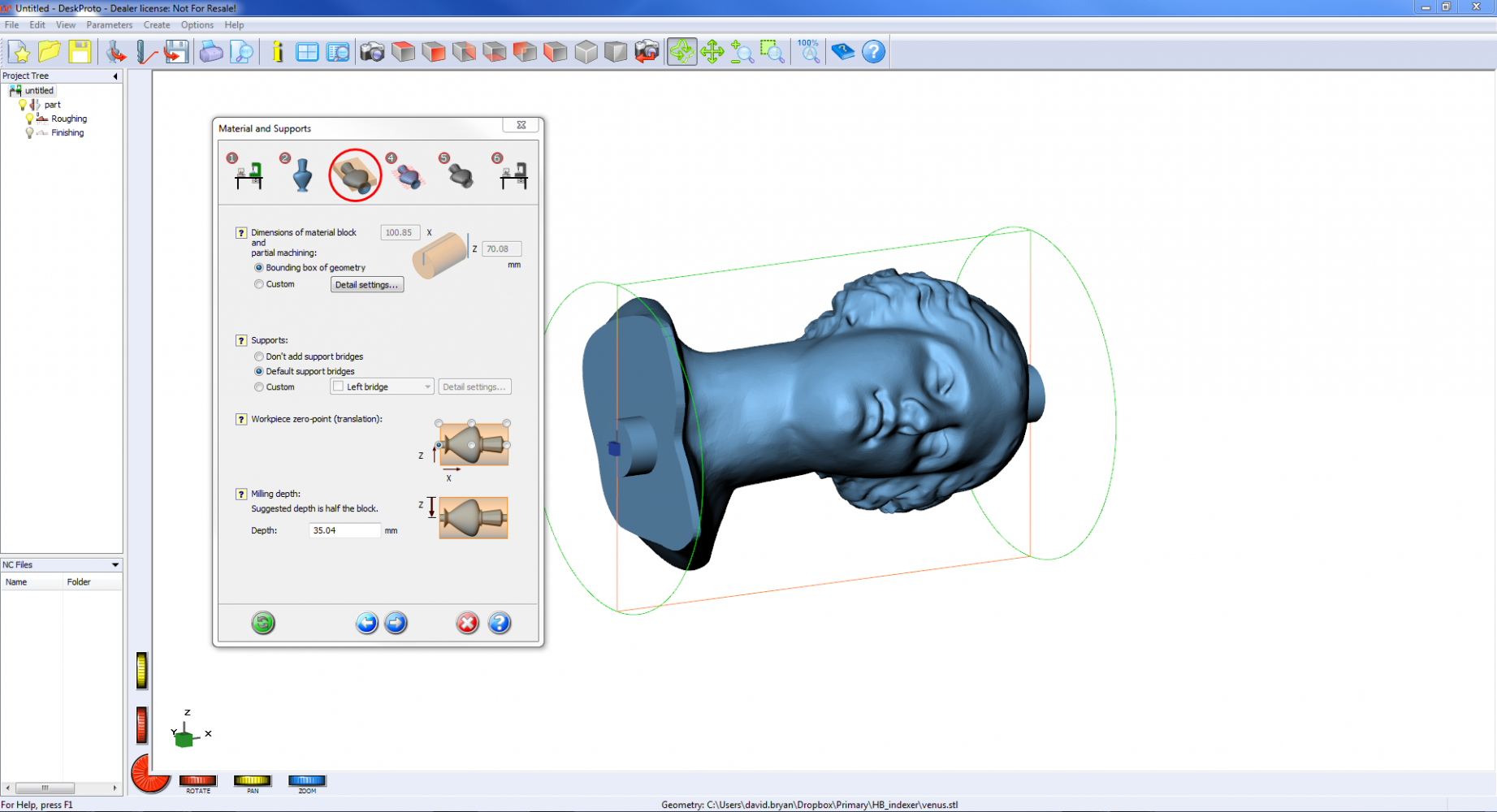
Use Bounding box of geometry and default support bridges
Mill depth should be set to half the depth of the block
Make sure your material matches these values
Click Next
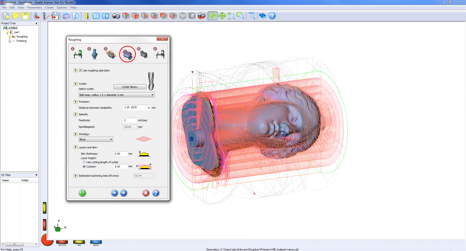
Check the box for Use roughing operation
I use an 1/8” ballnose cutter for this project
For roughing, I use the largest stepover available to help save time
Choose a feedrate, strategy, and layer thickness appropriate for your materials. I’ve chosen 2 inches per second, block, and 5mm for the poplar I’ll be using
After you have entered your chosen values, click the green button in the lower left corner for a machining time estimate.
Click Next
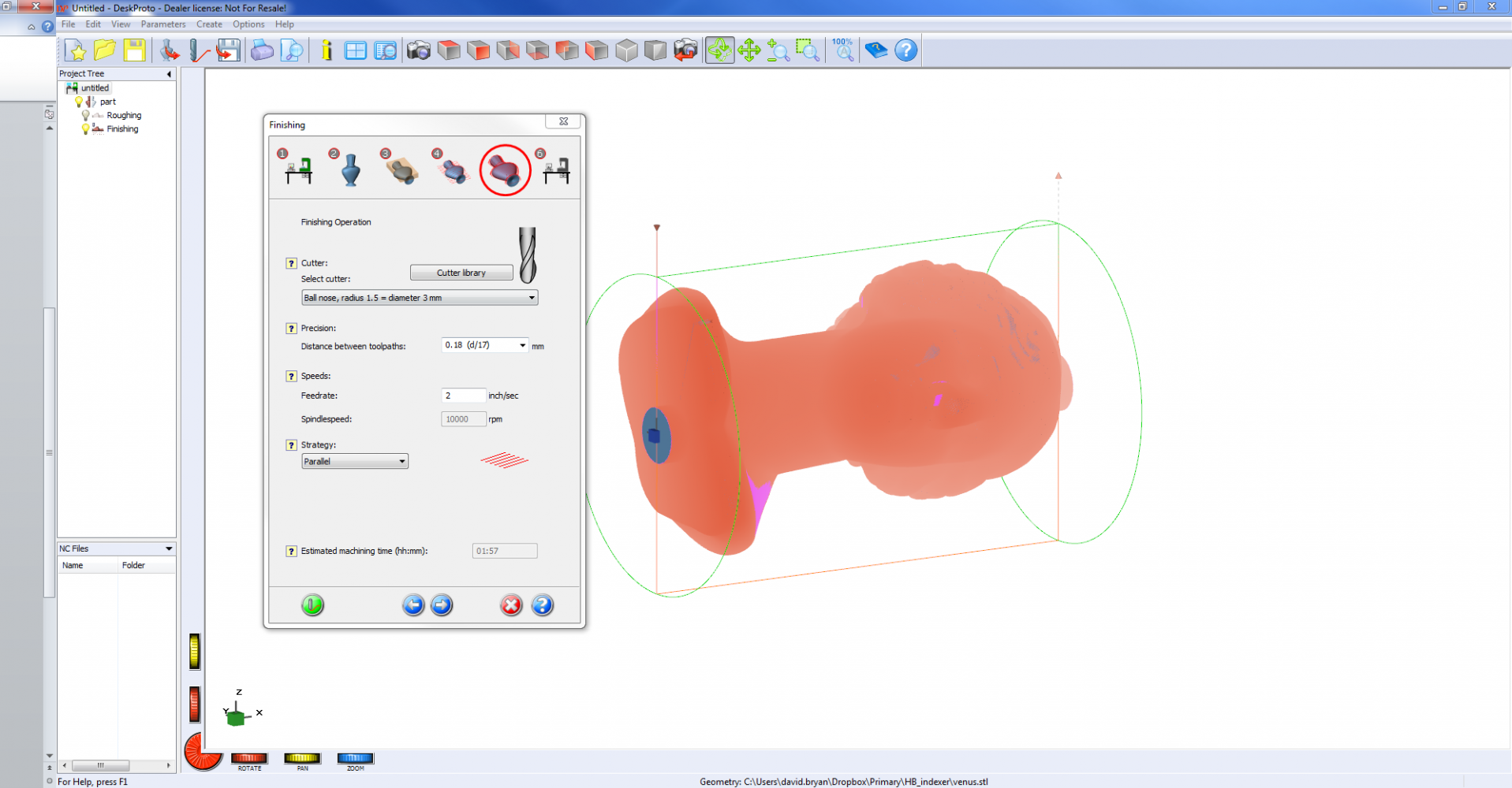
I’m using the same cutter for finishing to avoid re-zeroing the Z axis after changing tools between roughing and finishing. In some cases, a sufficiently large amount of material needs to be removed such that a larger cutter is needed to speed up roughing. In these cases, you’ll want to choose a finer cutter for finishing.
Choose stepover, feed, and strategy appropriate to your material
Use the green button in the lower left corner to estimate machine time
Click Next
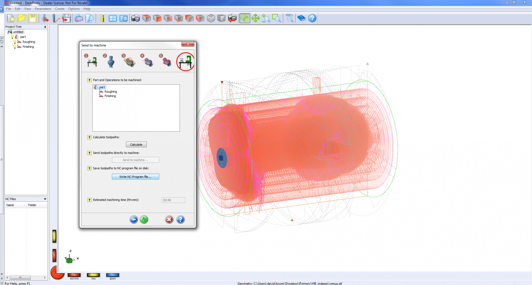
Click Calculate
Click Write NC-program file…
Save file and transfer to the computer that will run your tool
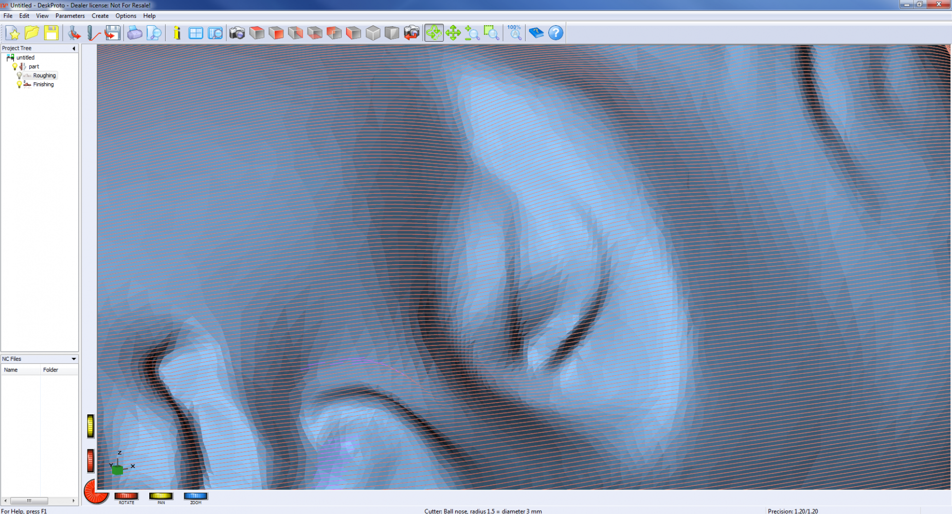
In the image below, see the tightly-spaced lines projected onto the model surface: these represent the toolpath.
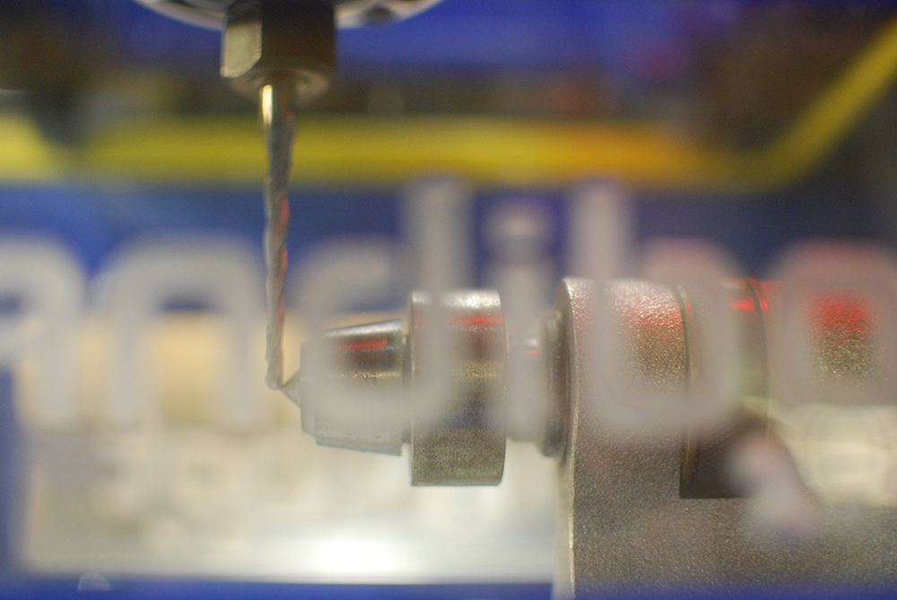
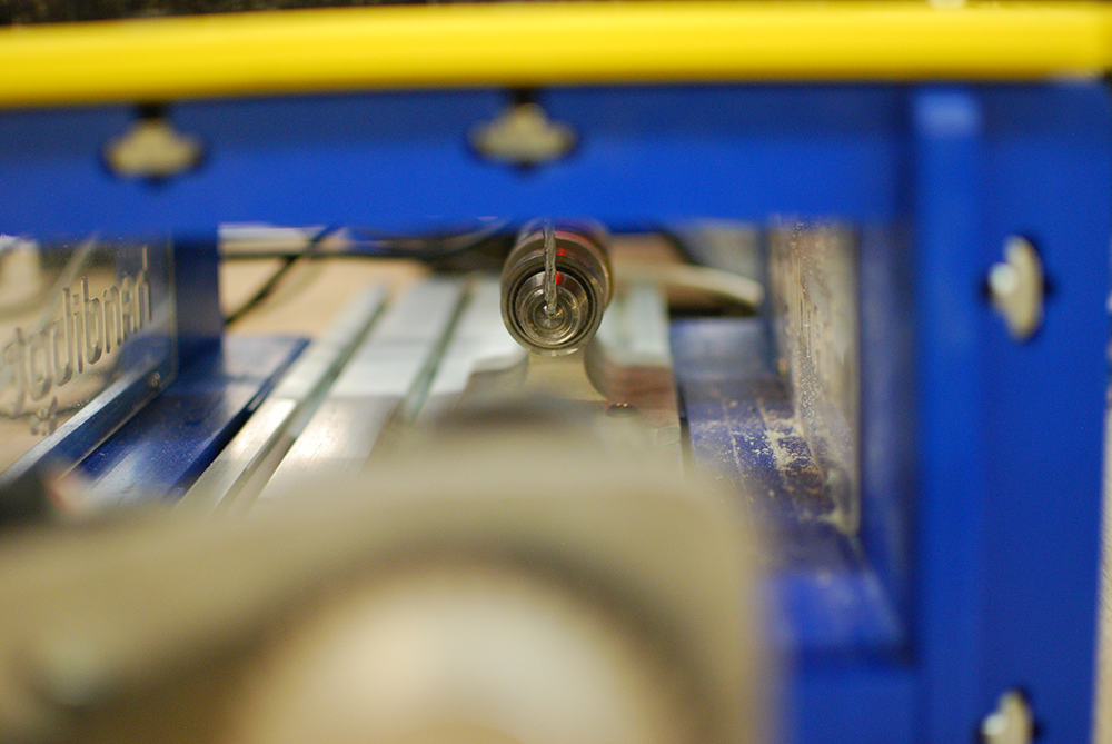
Now that we have a cutting file, we can move to the tool. First, we need to zero the machine so that the coordinates saved in the cutting file will map to the correct movement of the tool.
With the Handibot bolted to the 4 axis accessory, and no material blank loaded, zero the X and Z axes so that the tool tip is at the point of live center.
![]()
Mark centerpoint of blank on both sides
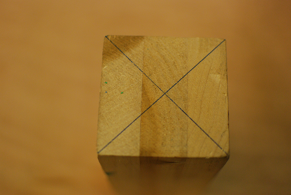
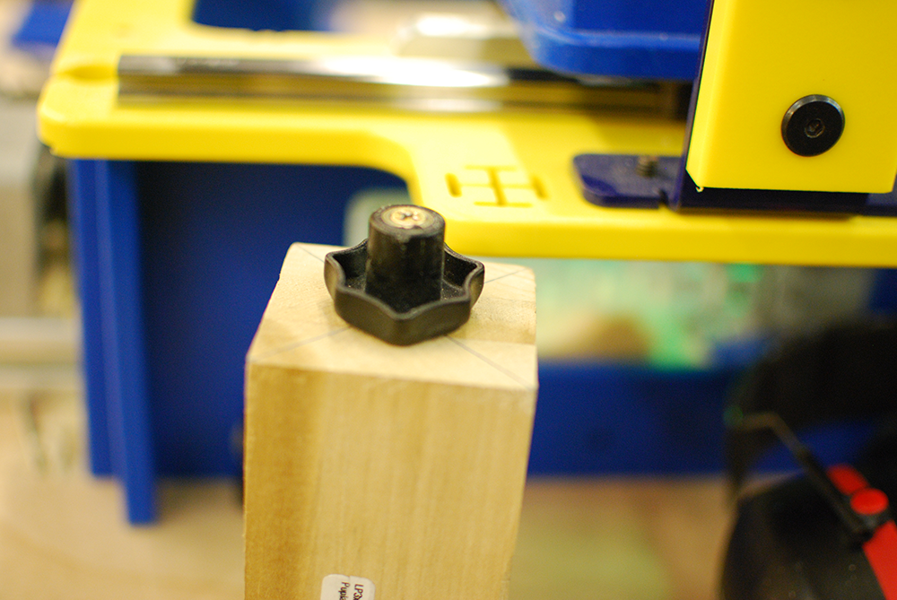
Here, I am using a knob to provide a griping surface for the indexer headstock since its jaws do not open far enough to gasp the material blank. Typically, a simple circular profile cut with your Handibot is enough to provide a suitable gripping surface. You want the axial centerline of your gripping form to align perfectly with the intersection of the corner lines marked on your material. Two additional short screws should be used to prevent the gripping form from rotation relative to the material blank.
Next, load the blank into the headstock. Loosening the knobs that hold the indexer extrusion in place make it possible to slide the extrusion to a convenient location for tightening the headstock. Once you have the material blank loaded in the headstock, tighten the headstock using the supplied rods.
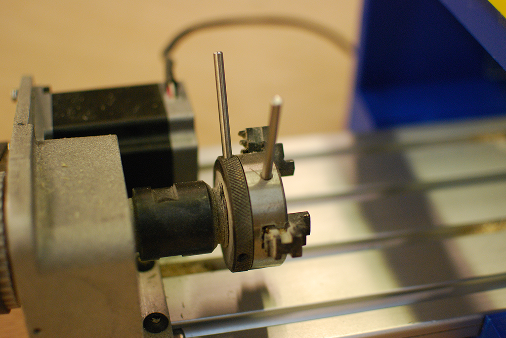
Next, slide the tailstock in the t-slots until it contacts the rear of the material blank. Take care that the live center point is driven into the blank precisely at the intersection of the corner lines. Apply firm pressure to the rear of the tailstock toward the headstock to ensure the material blank is stable while tightening the tailstock. Use a long hex key to firmly bolt the tailstock to the extrusion. Once both tailstock bolts are tight, use the knurled wheel on the tailstock to further drive the live center into the rear of the material.

Next, zero the Y axis forward of the material’s leading edge by slightly more than the length of screw used to prevent the gripping surface from rotating. This will prevent accidental tool collision with the screws.
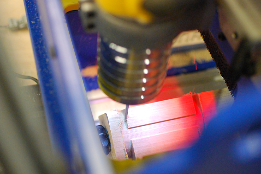
You are now ready to run your roughing file. The roughing file will remove material without touching the eventual finished surface of your model. Roughing the Venus sample here took approximately 40 minutes.
When the roughing is complete, run the finishing file. This file will take longer, generally, but will result in a smooth, finished surface. The Venus finishing file ran for approximately 2.5 hours.
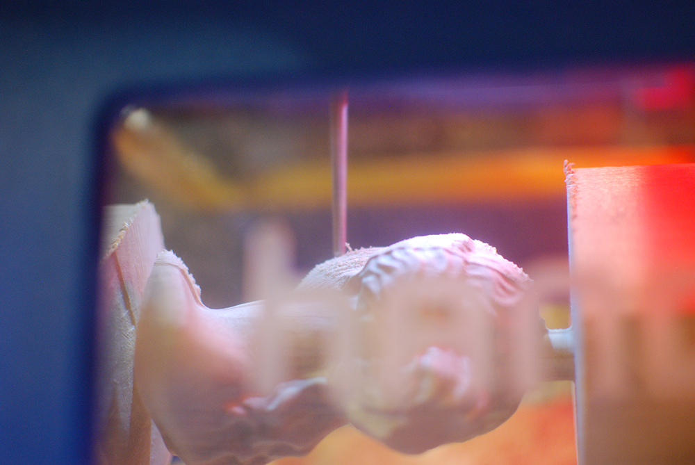
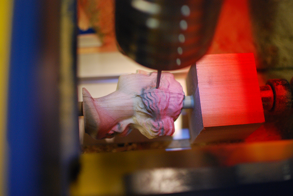
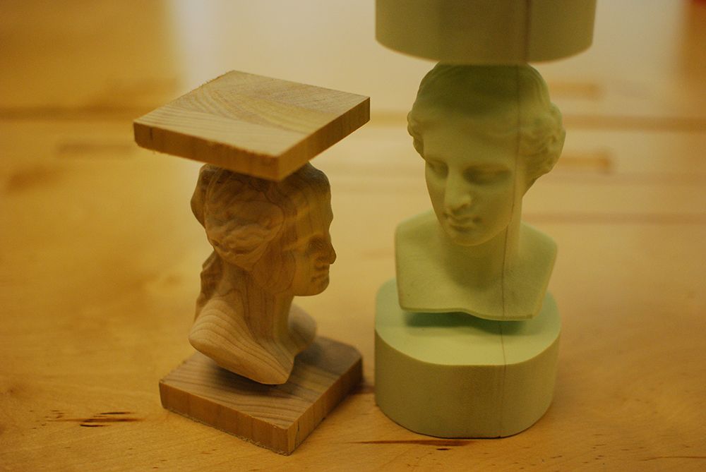
The finished surface is smooth and requires no sanding. The final model is pictured here with a foam test cut. Notice the glue line in the test cut where two thicknesses of foam were joined. Foam is a good way of testing toolpath that you aren’t sure of while reducing the risk of broken cutters.
In future Handibot Labs posts, we’ll cover how to prepare your Handibot for rotary machining, and how to use Cut3D for indexed-rotary machining. We’ll also be experimenting with linear indexing for rotary toolpaths beyond Handibot’s 8” of Y-axis travel.
While I am so excited for the advent of the 4th axis, I wander if you know what you have there in the plastic frame? with a few more parts it is a on edge joinery jig, a on end coinery jig, and a divider plate/muti side jig. All of which don’t need new electronics to work.
When can I have one now ?
Boris, we are very close. We have a nearly finalized design and are working with our vendors to source the parts that we don’t make ourselves. I expect to see these for sale in December.
David
Any update on this?
Interested in putting my hands on this rotatory indexer.
Hi John, We’ve recently tried to get some of the plans laid out.
https://handibot.com/blog/2015/01/development-team-report-january-2015/