Development Team Report / May 2015
by Brian Owen • May 28, 2015 • News
Bay Area Maker Faire 2015 –
The 15th annual Bay Area Maker Faire was held in San Mateo earlier this month and a good portion of the Handibot team traded the sweltering humidity of early summer Durham for the relative freezing cold of the Bay Area for a few days in order to show off the latest work on the Handibot platform. The ShopBot booth was anchored by the debuts of a couple of new products along with the reintroduction of a few upcoming things that have been in the works for a while.

The weeks leading up to Maker Faire were almost entirely consumed with iterations on a preliminary Handibot 2.0 design and tweaks to the FabMo control platform. This intense focus on design produced some interesting results that elicited some informative reactions from the folks that we met at the Maker Faire and we all came home with new ideas for continued work on these projects.

Handibot 2.0 –
I was both excited and nervous to demonstrate the latest version of the Handibot 2.0; excited because I knew that it would be refreshing to get some public feedback after bouncing the design around in relative isolation at ShopBot for a couple of months—nervous because my demo cuts on Friday morning would be only the second time that I had powered the machine on, and the first time ever with FabMo!
This prototype represents a complete, ground-up redesign of the Handibot; taking into consideration all of the improvements we’ve incorporated since the kickstarter campaign along with the feedback we’ve received from customers along the way. Our marketing director, Jeanne, filmed a quick video with me detailing the changes on display at Maker Faire and I will describe them here in more detail.
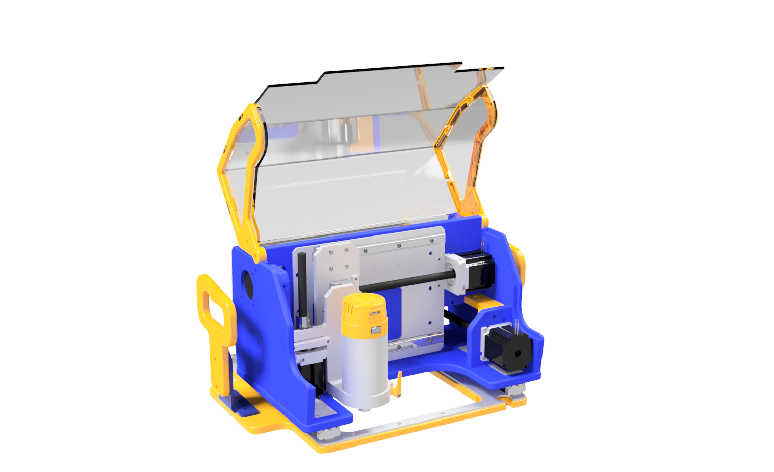
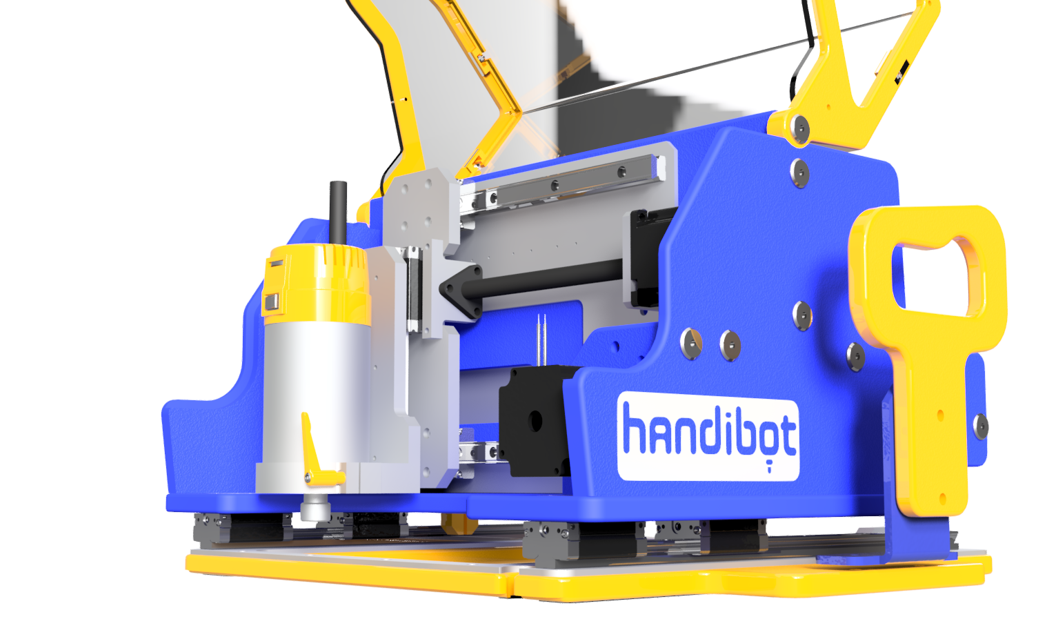
First, the most obvious change is the elimination of the front wall of the exoframe. This is something that we’ve wanted to do for a long time; it improves visibility of the tool and simplifies material setup, it also allows us to move the router forward in the Handibot frame in order to allow cutting to be done close to obstacles. Work to this end has been balanced by concerns about the rigidity of the tool. To address this we’ve designed the electronics enclosure in the back of the tool to serve a dual function as storage and as a structural component of the tool. The electronics dividing walls along with the mid-panel and rear panel form a rigid box section to which the X and Z axis assembly is bolted. The X and Z axes are now built onto an aluminum plate that can be aligned outside the tool and fixed in place later in assembly. We’ve also reinforced the base plate (and Y axis) with an aluminum plate to counter any torsion to the frame that might have become an issue with the open front design.
Second, we’ve made many of the upgrades and accessories from Handibot 1.0 standard on 2.0; aluminum backing plates for the Y bearings, reed-style limit switches for all three axes and an integrated hood that can be flipped down over the tool during cutting. We’ve been considering adding an optional safety switch that could be used to automatically stop the tool if the hood is opened during cutting.
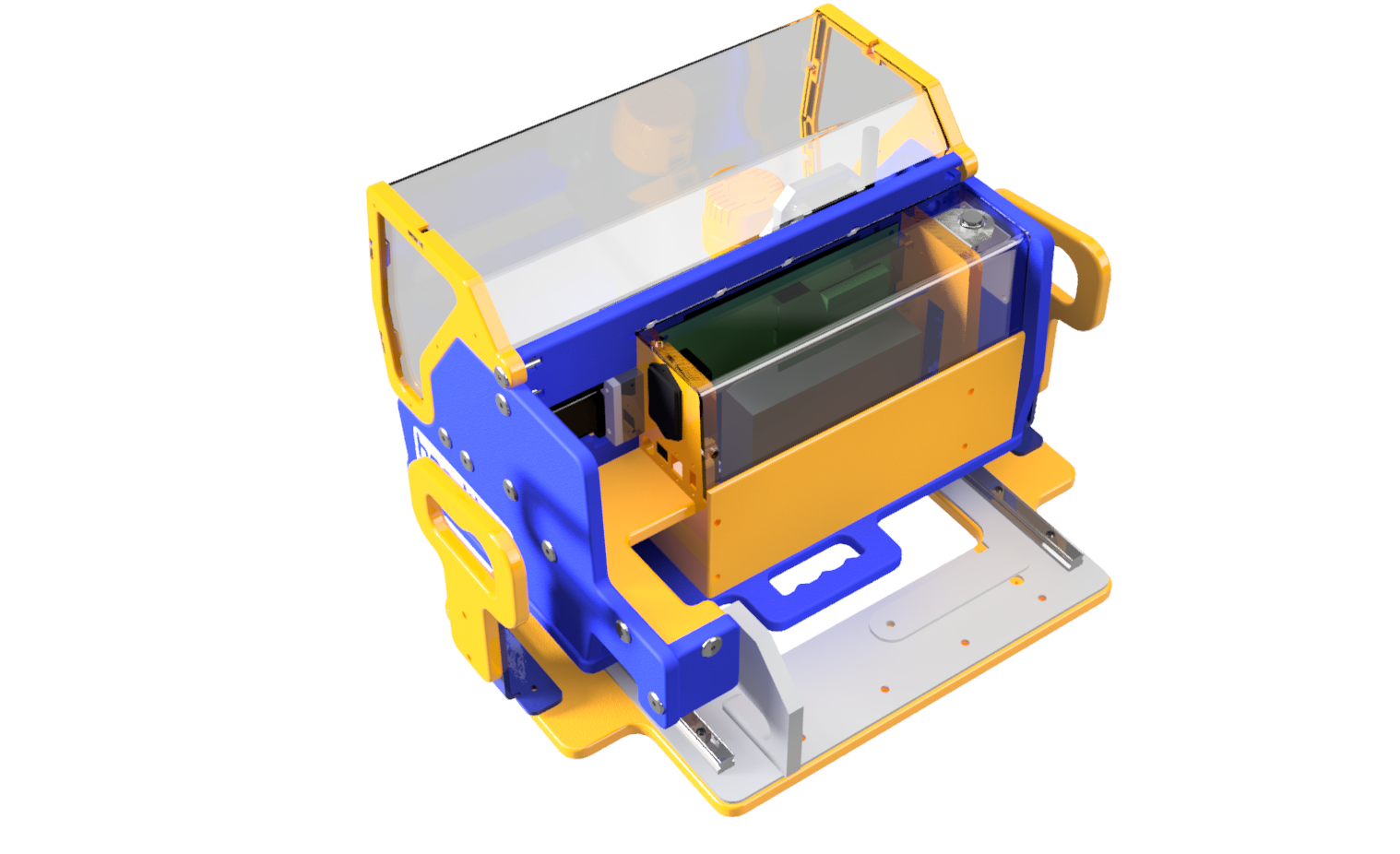
Anyone who’s ever opened the electronics enclosure on the handibot 1.0 knows that it can be a little tricky to work on with half of the electronics mounted to the cover and the other half to the machine frame with a web of wires spanning the gap between the two. With the addition of the aluminum backing plate for the X rails, we were able to flip the driver board around and mount every electronic component to the mid-wall of the exo-frame. This means that the electronics cover can be completely removed without disconnecting any wires, allowing easy access for tweaking or adding on to the control board. We also made use of the z-zeroing inputs in a way similar to what is used for our desktop tools. A small plate swings out from the base with a clip that can be attached to the bit. The standard z-zeroing procedure can then be used during tool changes.
FabMo –
There are others in the office who can speak at a much higher level about FabMo but perhaps my observations as a newbie to the platform are valuable to those outside of our development team. As I was packing up my prototype tool to ship off to California, Ted handed me a couple of circuit boards and cables thinking “wouldn’t it be cool if we could run FabMo on your tool during the show?!” So on the first morning of the show I loaded FabMo for the first time and sent my demo cut file to the tool’s new onboard computer over wifi. The cut file showed up in the web-interface’s queue and I clicked a small green button to run to the next file. My demo cut was a picture frame that required three separate toolpaths and a flip operation half way through. Once I had all three of these files loaded onto the Handibot I could re-run them repeatedly from my laptop or smartphone. While I was sending commands wirelessly to my Handibot 2.0, I was able to also simultaneously run my v1.1 and rotary axis over USB with the same computer.

In the meantime, Ryan was using a pair of FabMo Handibots to engrave the tops of our booth tables with geometric patterns and drawings from visitors to the booth. A FabMo app, written by Johnathan Ward, allowed users to draw their own designs freehand on a tablet screen and instantly carve them in an open space on the table. The fact that toolpaths are run from single board computers built into the Handibots allow one device to control a small army of tools without concern for communication interruptions—the only communication between the device and the tool are the start and stop commands. Ryan discussed some of the goals for the FabMo platform in an interview with Make:
Rotary Axis –
This product continues to creep towards completion. I had regrettably put it on the back burner in the past month to work on the Handibot 2.0 prototype. This time did allow for some interesting side-tracks which revealed additional uses for what we’re calling the “Accessory Base” that holds the rotary axis. Nate took the tool home one weekend to help a friend build a fence and was able to clamp the posts in place under the Handibot in order to cut the mortises: https://youtu.be/ooyDxoaRgBU
I’m currently building up an initial run of the Accessory Base to prepare for release. I’ve uploaded the 3D model to AutoDesk’s Fusion 360 and it can be viewed or downloaded here.
Impressions from Maker Faire –
-Rotary Carving as an alternative to 3D printing…small stepover allows for an amazing finish on turned plastic parts. There are some physical limitations to what can be created by turn milling; but what it can do, it does well. People seemed most interested in the smooth finish on the candlestick holders I was carving.
-Machining aluminum with Handibot 2.0…A lot of the visitors to our booth were interested in making machines of their own, either as part of robotics clubs or for more entrepreneurial applications. One of the big benefits of a stiffer Handibot frame is an improved finish on milled aluminum parts. Paired with the Accessory Base and a small mounted vise, the Handibot could be a useful tool for small robotics components.
-Dust collection is a big concern for a lot of users. The Handibot 2.0 prototype had no dust collection to speak of and spent the show spewing chips every which way. Ted has been working on a dust foot design that is similar to the style used on our desktop tools where a domed dust foot is mounted to the router itself in order to create much more effective suction when paired with a small shop-vac. This will be incorporated into the final version of the Handibot 2.0
Feedback on our work is always appreciated, so don’t hesitate to leave a few comments or questions based on the details that I’ve shared here!