A Boat Hardware Project: And, Oh … for a Toolpath-Generating QR Code!
by Ted Hall • July 5, 2015 • News, Projects
A job well suited to Handibots is machining cut-outs for hardware items of one sort or another – – brackets, outlets, hooks, fixtures, lamps, switches, controls, handles, etc. My Handibot was particularly useful for just that type of job on a recent boat project.
Project Details
I had broken the pull-ring for a floorboard hatch on my boat. The only replacement pull that I could find was larger than the original hardware and needed a larger cutout. Marine hardware is a particularly good example of parts that frequently need specialized cutouts for mounting in bulkheads, decks, and panels. Here’s my new part and the floorboard, with the old hole, that I needed to put it in. You’ll note that the necessary hole for this part is actually a 3D pocket type of thing, not just a cutout in a panel.
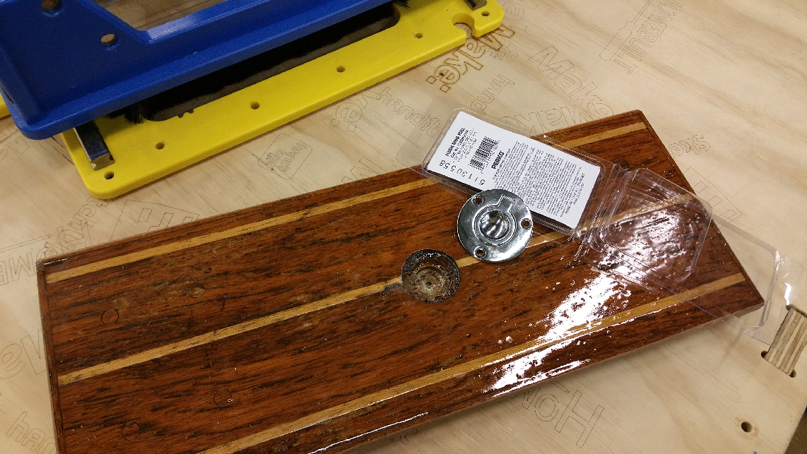
My floorboard with old hole and new part.
The Toolpath
We can hope that, someday, manufacturers will be providing machining information that will allow “smart tools” like Handibots to quickly machine a mounting area or cutout for their product – – perhaps after just allowing us to scan a QR code on the packaging! Someday …
Out of perverse curiosity, I wrote the manufacturer of my part asking for a CAD or CAM file… I think they thought I was joking. Thus alas, no instant toolpath. And, in fairness, as the part was probably made with an old, pre-digital, casting it is not surprising that they did not even have a CAD file for me. So what would be the best and fastest way to create the new, 3D, cutout shape for housing this pull-ring?
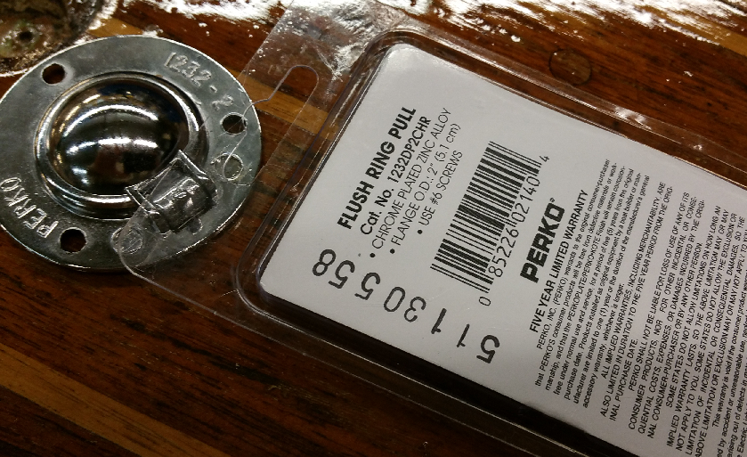
Someday, we’ll get the needed cut-out from the QR Code on the package or part.
Scanning the part did not seem the best approach. In the absence of a ready-to-run tool-path from the manufacturer, scanning or digitizing the part and creating a tool path from the new digital model would be one approach that could be useful for a lot of cut-out jobs. In this case, I didn’t think scanning was right. To scan, I might use a service like the 123D-Catch-tool provided by Autodesk. Using 123D Catch would involve taking a number of pictures of the pull-ring from many different angles, uploading the images to Autodesk’s cloud server … and a little while later, receiving back a 3D model. The 123D Catch system is pretty cool and it’s free. I’ve had it work well in a number of cases. For the back of the chrome pull-ring, to get a good model, I would have probably needed to first spray-paint a matte color to prevent miss-cues from all the reflections.
A more physical approach to scanning would be to digitize the part with something like the ShopBot digitizing probe that can be chucked up in a Handibot and, using the “CopyMachine” tool [TC] in the software, can produce a surface map my touching off the surface in small increments.
The problem with both modeling approaches is that they are a bit overkill and they prioritize getting the shape of the back of the part perfect. I wanted to prioritize getting a crisp, perfect fit where the pull sat in the surface of the floorboard. I didn’t really care about the shape of the hidden, back-side of the pull ring as long as I took out enough material for clearance.
So, just using conventional CAD to CAM seemed the most straightforward. I used calipers to measure the diameter, depth, and other details of the pull-ring and focused on making a perfect countersink for the outer ring. To accommodate the sunken part of the pull, I just made sure I pocketed out deeply enough for good clearance. I used the V-Carve Pro software that is shipped with Handibots to draw the machining perimeters; then tool-pathed with its CAM functions. This gave a machining path that looked like this in preview.
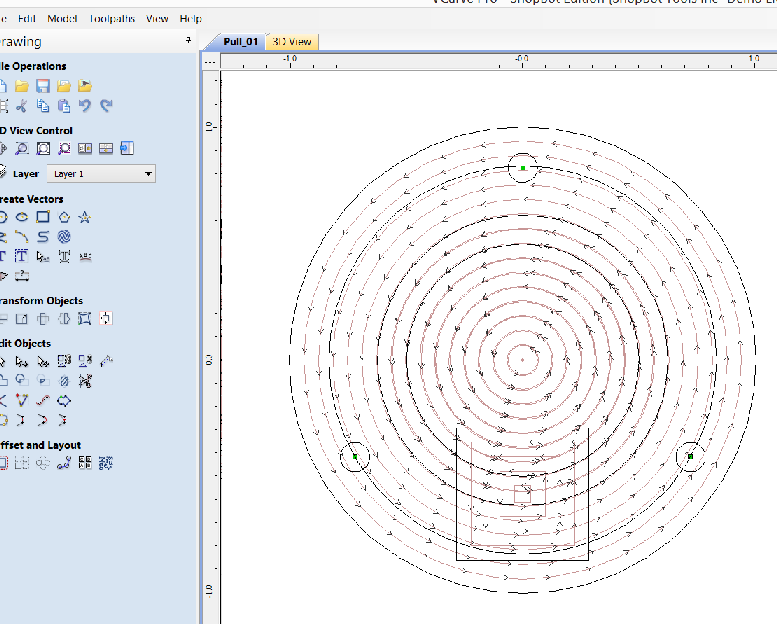
Tool-path inV-Carve Pro.
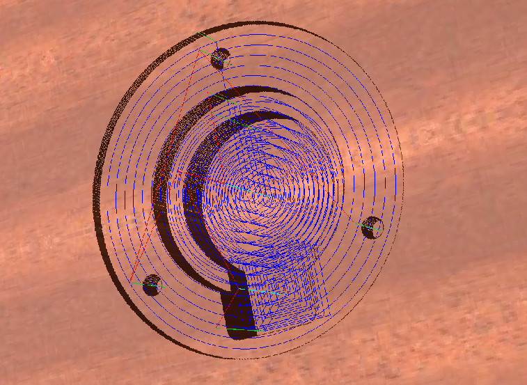
The simulated pocketing.
Machining the New Hole
Since I could not afford to mess up my only floorboard, I did a test cut in a scrap before attempting the real cut … it looked good. So I moved on to the real piece.

Practice cut …
When I created the toolpath, I set the 0, 0 location to the center of the part so that I could use the “Laser-Site” accessory to position exactly over the old hole — except I moved it forward slightly so that I could machine over a slight tear-out in the wood from the previous work.
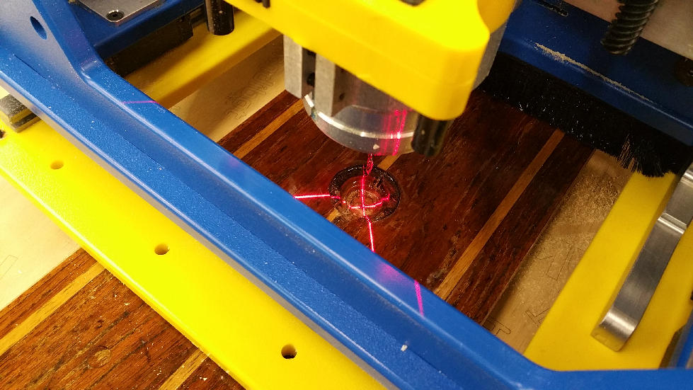
Using Laser-Sight to position the cut-out.
Then I was ready to do the job. Here’s a little video of the cutting.
With the final, perfect fit, in the floorboard.