Joinery (part 1)
by Brian Owen • December 4, 2017
Joinery is the targeted application of stress and the employment of friction to turn two components into one object.
The stress part seems obvious to most people–they feel the energy they put into twisting a screwdriver turning into pressure on the board they’re bolting down to the floor. The friction component is just slightly less obvious and, at least for me, can be too easily overlooked unless you stop and think about it.
The screw that you’ve driven through the board and into the floor is not just preventing the board from being lifted up—it is preventing it from sliding. The screw is doing this by pushing down on the board which creates friction with the floor. You cause the screw to do this by twisting it—digging its head into the slightly springy wood and even stretching the screw a tiny bit as its threads cut into the floor and pull it downward. That stress that you induce in the screw, board and floor will hold the whole system in place as long as it is maintained. But if the board rots or the screw rusts or the floor crumbles—the stress will be released and the friction will evaporate and the joint will be broken.
Stress is induced in all components of the joint and is necessary for a rigid form.
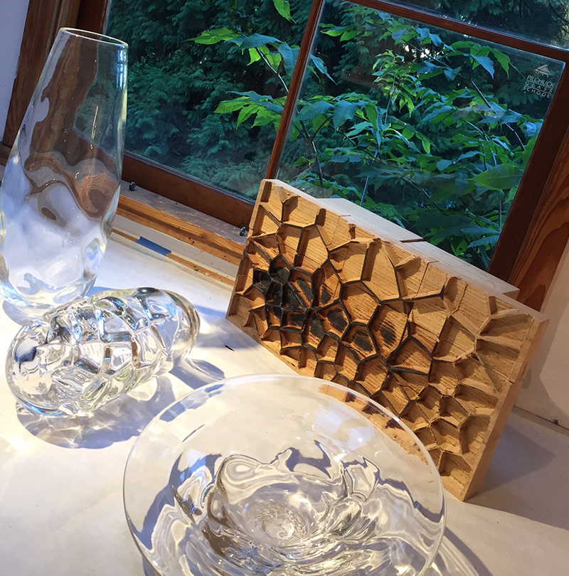
This equation exists in any joint you can imagine though sometimes in a different arrangement. A tenon is stretched as you pound a wedge into it. Friction resulting from the tension holds the wedge and the mortised board in place. Even a glued joint is held mechanically by long polymer chains that are formed as the glue dries inside the pores of the wood—expanding the fibers and creating friction between the wood and the hardened glue. Try looking around at examples of joinery in your immediate area and imagine how stress and friction play a part in making the joint.


https://i.stack.imgur.com/7L9fx.jpg
Your job now, as a designer, is to lay out the criteria for your joint. Do you want to be able to disassemble the parts later? What tools will you or others have available when assembling the joint? Worst case scenario…would you rather the joint or the components break when placed under extreme stress? Thinking about these things will cull your options most quickly. Screws are great if you want to take the joint apart later…but they are relatively expensive…and they may vibrate loose at the worst possible moment. A glued joint is great for something that you’re building in your shop…but you would never send your customer a little tube of glue to assemble your product. Nails are a lot stronger than wood—so you can expect a lot of splintering if the joint fails under stress.
With your constraints defined, your next step is to determine how you are going to apply stress and create friction in your joint. Let’s assume you’re going to use screws. You’ll need a good amount of surface area shared by the two components being joined. If you’re going to be joining things at odd angles you may even need to cut angled faces into your components so that there is enough flat area to make the joint. Not only that—you’ll need to be able to apply forces perpendicular to those faces with your fasteners. So—for every angled face being bound to another—you’ll need a corresponding angled surface on which to fasten the screw.

Before we get too exhausted keeping track of this network of paired faces and alternate interior angles…let’s consider the mechanism of the screw. The screw creates stress by sliding into a material along angled threads as it is twisted. Wood screws cut their way into a board as they are twisted—while most metal (machine) screws are twisted into pre-formed threads made during a separate process. Either way—the tension in the screw increases based on the torque applied to it. Applying torque to the screw easily spins it into a hole as the force applied is nearly parallel to the face of the screw threads. The tension forces on the screw, however, are unable to spin the screw back out because those forces are nearly perpendicular to the screw threads—creating a huge amount of friction between the screw and the material into which it has been driven.

The screw joint will fail (catastrophically!) in one of two ways—failure of the screw or failure of the components. If you’ve ever torn apart an old piece of furniture with a crowbar, you’ve probably seen both types. A screw can be put under such tension that it snaps in half—or you can pull so hard on a screw that the components themselves fail and the screw tears out of the board. Remember—the screw is only holding onto the board by that little bit of material that it has cut into with its threads. An ideal joint is not going to leave much on the table in either direction—the force that would break the screw should be pretty close to the force that would be able to tear it out of the material. Otherwise, why bother with the weight and expense of the screw?
This is all really basic for anyone who has ever tried to build anything from wood—but I bring it up as a preface to talking about where all of the really fun design work in CNC joinery gets done! How do you join two relatively weak materials using common screws to create a joint that will stand the test of time, abuse and repeated assembly and disassembly? In all likelihood, the screw is not going to fail—it is much stronger than your material—the joint will fail when the screw strips out of the material. So the only thing to do is give the screw more material to hold onto!
The simplest way to do this would be to use a longer screw. A screw twice as long will cut twice as far into the board and thus have twice as much wood holding it back from tearing out. But this is only practical up to a point. You can’t very well drive a 4” long screw into a ¾” thick board—for one, there literally won’t be any wood surrounding 80% of the screw—and two, you’re going to get poked in the butt by that screw every time you try to sit down in your newly built chair! The same goes for simply using a screw of a larger diameter—only useful up to a point. What if you need a joint that is 4 times stronger than a regular screw joint? Or 10 or 20 times stronger?
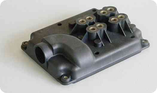
What if instead of driving the screw directly into the wood, we drove the screw into another, larger piece of metal and embedded that metal in the material we’re trying to join? Take apart any of the plastic power tools you own and this is exactly what you’ll find. The plastic body of the tool has been cast around a metal threaded insert. When the two halves of the body are assembled, the screws are driven into the inserts and the inserts are well embedded in the plastic body. The force that would be required to tear that insert out of the plastic is much closer to the ultimate strength of the screw itself—making it very much a well-designed joint.
http://www.myplasticmold.com/insert-moulding
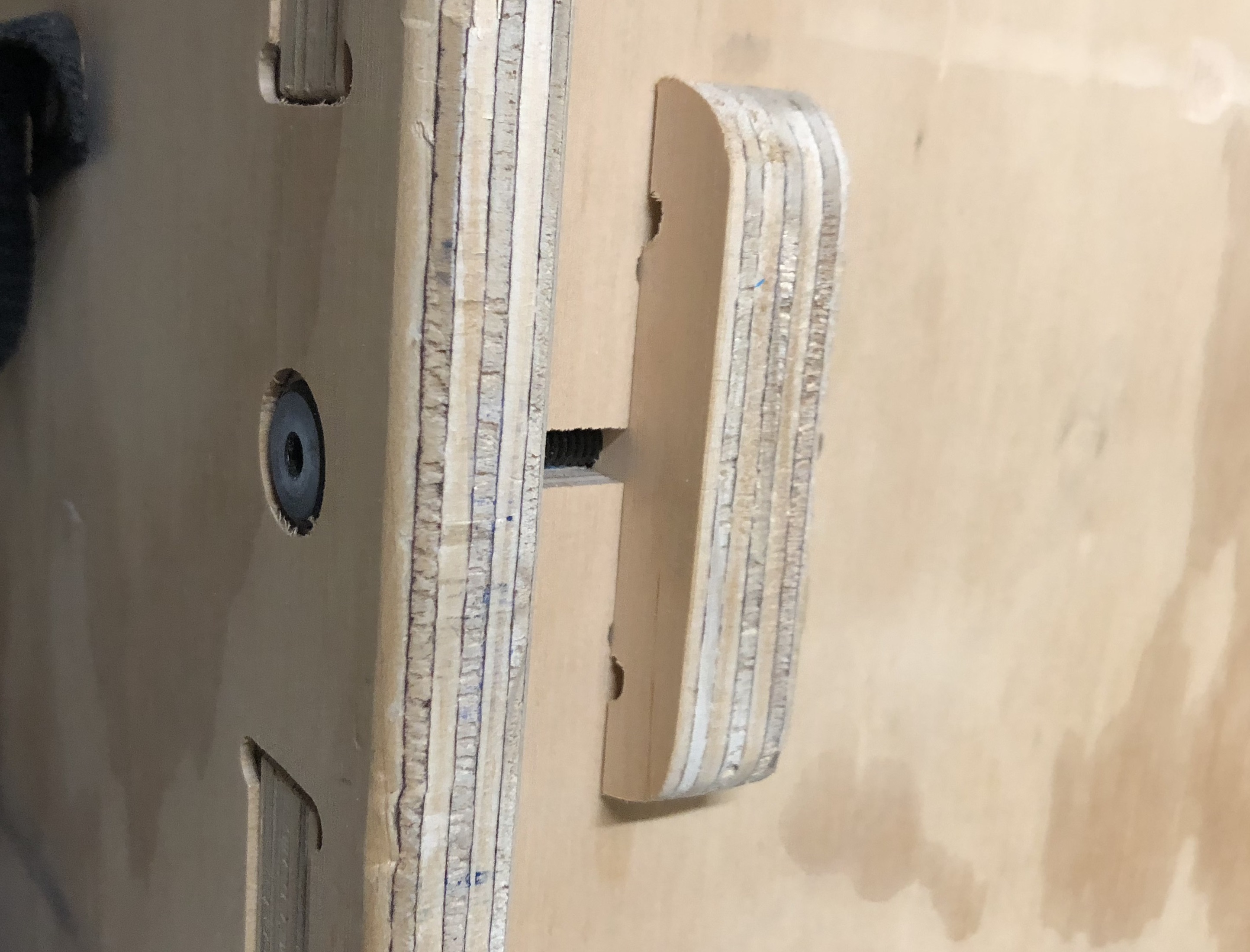
But you aren’t going to cast your part—you’re not making 10,000 of something, you’re making 10. Instead, you’re going to design and cut a pocket into your part, which will provide a spot into which an insert can be pressed, which will line up perfectly with the path your screw takes as it enters the joint.

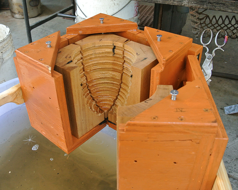
http://www.waterfront-woods.com/Projects/RoundTable/TableBlog12.html
What to use as an insert? The bigger the better—we’re working with soft materials here; it’s going to be pretty tough to design a joint that will make the screw fail first. Take a look around your hardware store at metal things that have threads cut into them. There are all varieties of nuts and threaded plates—some designed for this purpose others not, it doesn’t matter as long as you can picture them fitting into the part you’re designing.
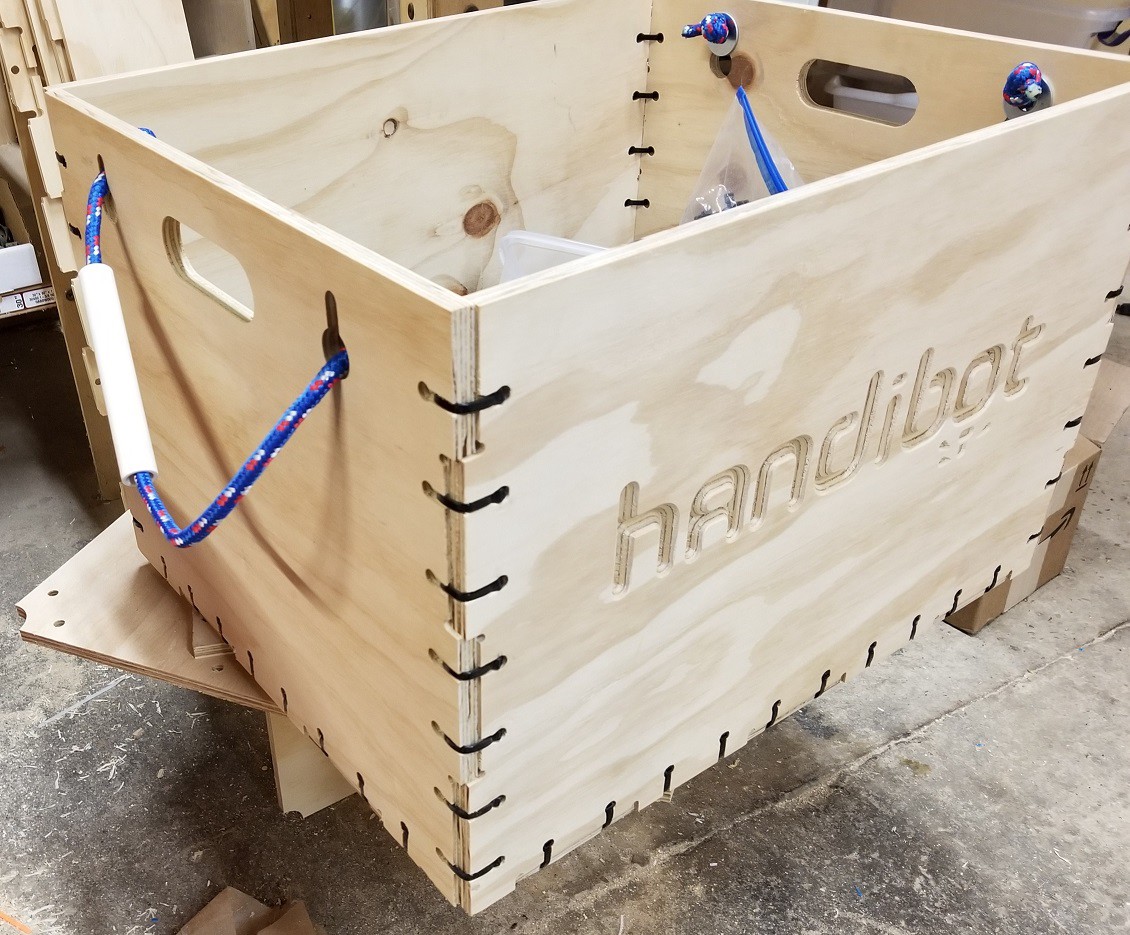
Joinery from Version 1 of Handibot.
The McMaster-Carr catalog has been the best design tool I’ve ever known—whenever I don’t know how I’m going to build something, I start to look at random pages in the catalog until something jumps out at me. Most of the time it will be something totally unrelated—a part or device I’ve never even heard of before. As I look at the tidy black and white drawings of parts I realize that one of them will do exactly what I need, and save me a lot of work and money in the process.
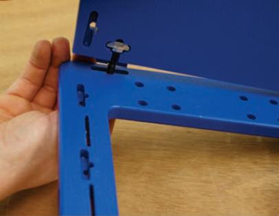
Zip-Tie joinery designed by Bill Young.
Don’t be limited by the thought that the insert can only be pressed into the component being joined. Sometimes you won’t be able to find an insert that is adequate for the joint you’re trying to make—it’s still too small and the forces on the joint are too large. You may be able to design a third component of the joint—a doodad that firmly holds the insert and then itself is dropped into place on the component you’re trying to join.

“Telephone” joint designed by Bill Young using a Tee-Nut and wooden insert.
\
This becomes especially helpful when working with non-isotropic materials—like wood! The grain in most woods means that you’ll have a lot of strength in some directions but very little in others. So what to do when you need to join something along the weak axis of the wood? Drop in another piece of wood, oriented in the strong direction and drive your fastener into that piece.

Grain tear-out
Insert with rotated grain.
Now that we’ve thought about ways to multiply the force held by our joints—let’s do some more visualization of the stresses in our joinery. It is important to imagine where the joint is going to fail. Figure that out—and then solve that problem—restart the process and find the next weak point—solve that problem…and so on.
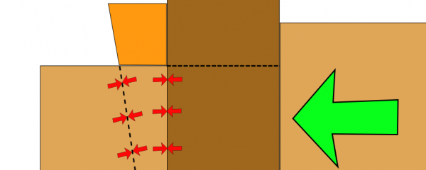
Assuming that the materials you are using have more or less consistent strength—it is probably going to be the area where the material is thinnest that will fail first. We take advantage of this fact all the time—the waffle-iron pattern of chocolate bars or the perforated line on a movie ticket.
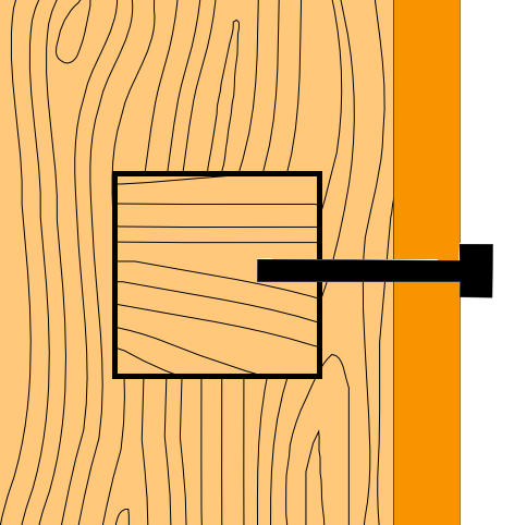
It can help to draw your part out on a piece of paper. Draw lines connecting the boundaries of the part through the thinnest regions. The lines should represent the area that would need to crack in order for your joint to come apart. Now draw lines parallel to the direction your screws will be inserted. If those two sets of lines are parallel to one-another and very short then you’re in trouble! Find some way to either make those “thin boundary lines” longer, or to redirect them perpendicular to your screws. Thin boundaries are bad news no matter where they are—but most materials are much stronger in tension than in shear.
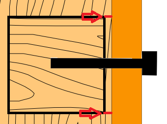
Bad!

Good
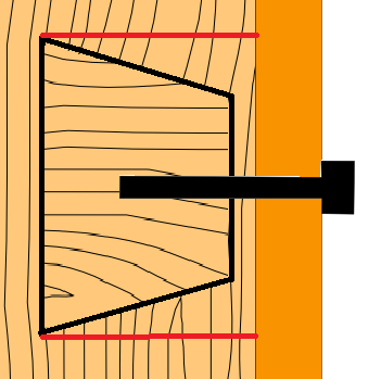
Better!
Most materials are flexible up to a point—and most of those materials will spring back into shape after being bent. However, past a certain point, elastic deformation stops and permanent plastic deformation begins—further past that and cracks begin to form and expand. Once your material is cracked, those thin areas quickly become thinner as the crack races through that line (the one you just drew across the thin boundaries) and your part breaks.
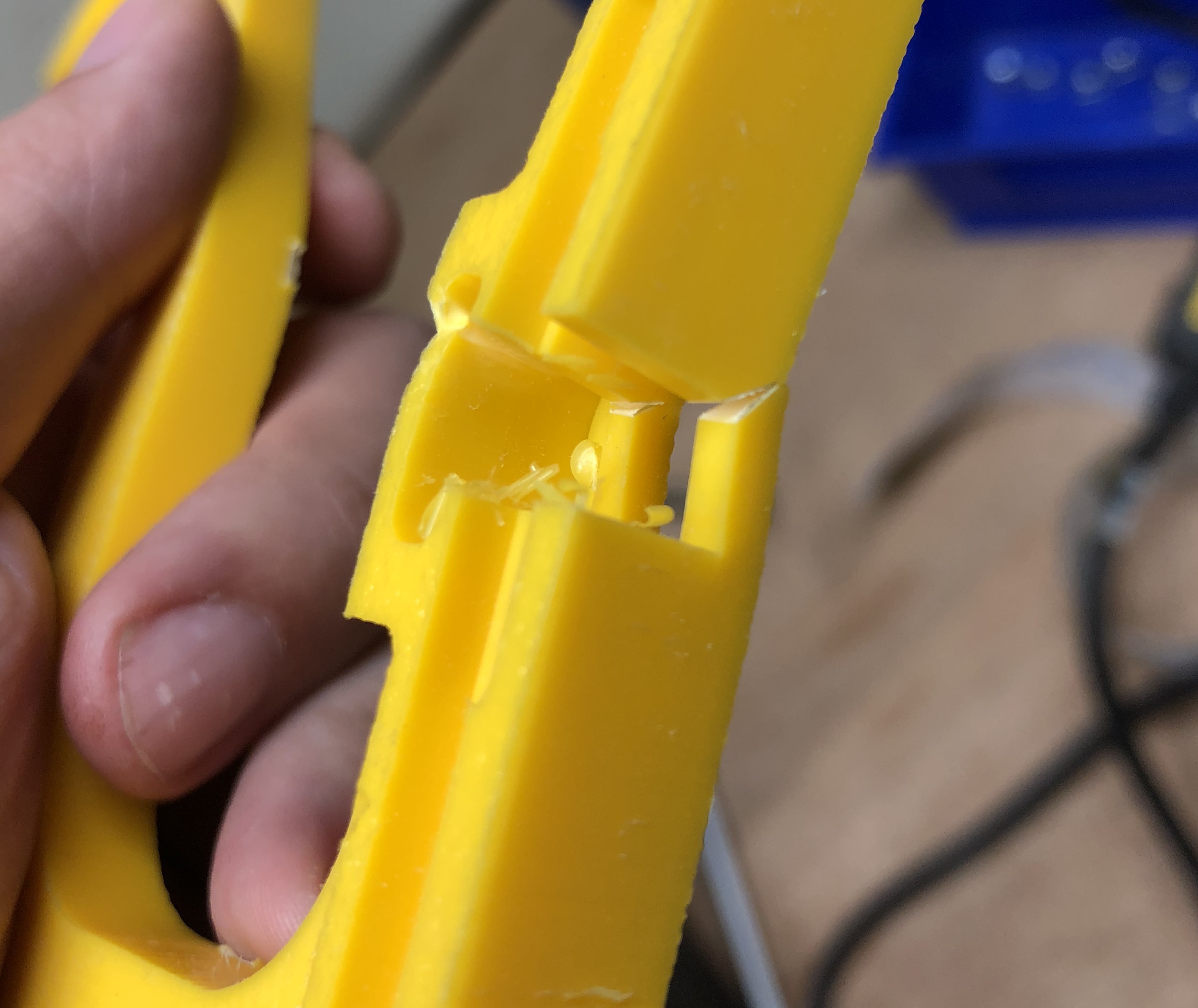
Once a crack starts you can go ahead and declare your joint as failed. But where exactly do cracks start? A crack must start in one single place—why that place and no other? I may be alone in this but I still sometimes puzzle over this pseudo paradox—if I were to add stress to a joint, one iota of an ounce at a time; one of those iota would be the difference between apparent stability and imminent failure. But how could an infinitesimally small increment of weight make that difference? And if it were impossible for a single straw to break the camel’s back, shouldn’t I be able to go on adding weight forever?
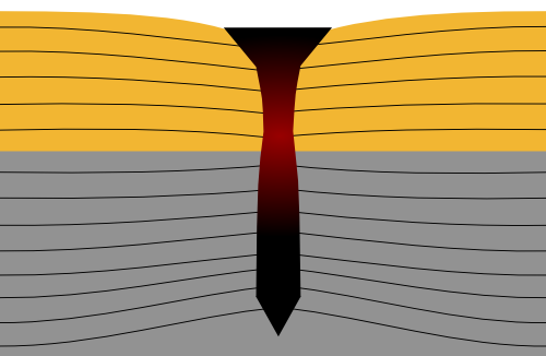
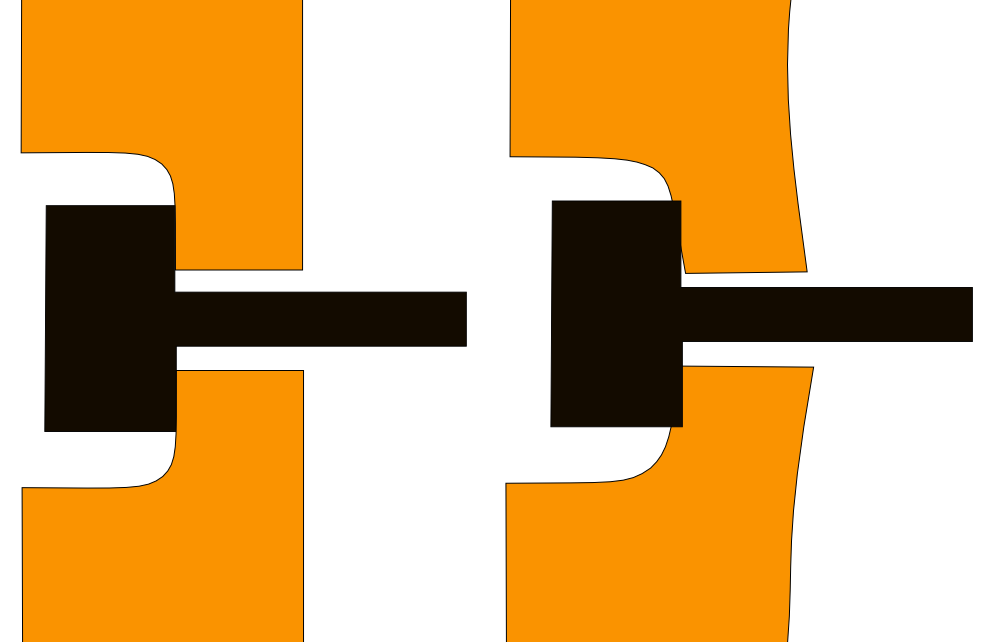
In fact, cracks are all over the place. Microscopic imperfections in the surface of your material—either naturally occurring or created by the tool you used to cut the material pervade the surface and interior of your parts. On the macro level, these are your sharp corners and acute angles. When a big crack starts to form, It will almost always be on the inside corner of an area under stress.
Referred to as “stress concentrations” or “stress risers”—these areas can be visualized by imagining stress as a fluid that flows through your parts. Sharp corners and acute angles create concentration points (eddies?) in the flow of stresses through the part. One of the microscopic cracks in these stressed areas will eventually grow and cause the part to fail.
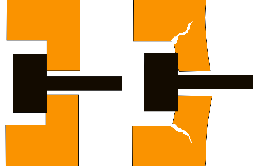
To avoid this, you should design your joints with rounded interior corners. This is almost inevitable when cutting parts on a CNC mill—the round bit will limit the minimum radius of an interior corner according to the diameter of the bit. However, the square end of the bit will leave perfectly sharp corners at the bottoms of pocketed areas. If you’re seeing cracks on the back side of a pocketed area and those cracks roughly line up with the inside edges of the pocket—then you might consider using a ball-end mill (a bit with a rounded end) to make your pockets.
Finally—let’s address the longevity of joints. All joints will eventually fail. The mortar between bricks crumbles, wood rots, metal corrodes. You must consider the properties of the material and whether it will be able to stand up to the stress you’ve induced in it over the long term. The joint may hold fine today—but how about after a year in the sun or in your cold garage?
Temperature fluctuations will exercise cracks in your materials causing them to grow little by little every day. Sunlight will slowly destroy plastics. Materials like HDPE (High Density Polyethylene) will become more brittle as they age and “dry out”.
The design of your joinery should take this into account and provide excess strength now in preparation for a later time when your material or fasteners might not be so strong.
In the next part of this series—I’d like to start getting into the specifics of how to design a joint that will be easily cuttable with CNC equipment. CNC is a vastly enabling technology but there are still a number of limitations—the observance of which will allow you to consistently and quickly create useful parts. Thanks for reading and please leave comments and questions!